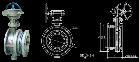
Telescopic butterfly valve

| SD |
t
d |
343 |
H
F
X |
- |
6
10
16 |
系列链接尺寸Series connection dimensions |
|
公称通径DN Nominal diameter |
结构长度(标准值) Structure length (standard) |
连接尺寸(标准值) Connection dimension(standard) |
|
毫米mm |
设计 最大 长度 Lmax Most desing extent |
设计 最小 长度 Lmin Least desing extent |
安装
设计
长度
L
Desing
extent |
PN0.6MPa |
PN1.0MPa |
PN1.6MPa |
|
D |
D1 |
D2 |
Z-d |
D |
D1 |
D2 |
Z-d |
D |
D1 |
D2 |
Z-d |
|
50 |
186 |
156 |
171 |
140 |
110 |
88 |
4-14 |
165 |
125 |
99 |
4-18 |
165 |
125 |
99 |
4-18 |
|
65 |
190 |
160 |
175 |
160 |
130 |
108 |
4-14 |
185 |
145 |
118 |
4-18 |
185 |
145 |
118 |
4-18 |
|
80 |
198 |
166 |
182 |
190 |
150 |
124 |
4-18 |
200 |
160 |
132 |
8-18 |
200 |
160 |
132 |
8-18 |
|
100 |
228 |
188 |
208 |
210 |
170 |
144 |
4-18 |
220 |
180 |
156 |
8-18 |
220 |
180 |
156 |
8-18 |
|
125 |
240 |
201 |
220 |
240 |
200 |
174 |
8-18 |
250 |
210 |
184 |
8-18 |
250 |
210 |
184 |
8-18 |
|
150 |
246 |
206 |
226 |
265 |
225 |
199 |
8-18 |
285 |
240 |
211 |
8-22 |
285 |
240 |
211 |
8-22 |
|
200 |
265 |
219 |
242 |
320 |
280 |
254 |
8-18 |
340 |
295 |
266 |
8-22 |
340 |
295 |
266 |
12-22 |
|
250 |
295 |
240 |
267 |
375 |
335 |
309 |
12-18 |
395 |
350 |
319 |
12-22 |
405 |
355 |
319 |
12-26 |
|
300 |
308 |
254 |
282 |
440 |
395 |
363 |
12-22 |
445 |
400 |
370 |
12-22 |
460 |
410 |
370 |
12-26 |
|
350 |
327 |
272 |
300 |
490 |
445 |
413 |
12-22 |
505 |
460 |
429 |
16-22 |
520 |
470 |
429 |
16-26 |
|
400 |
368 |
308 |
338 |
540 |
495 |
463 |
16-22 |
565 |
515 |
480 |
16-26 |
580 |
525 |
480 |
16-30 |
|
450 |
370 |
310 |
340 |
595 |
550 |
518 |
16-22 |
615 |
565 |
530 |
20-26 |
640 |
585 |
548 |
20-30 |
|
500 |
392 |
332 |
362 |
645 |
600 |
568 |
20-22 |
670 |
620 |
582 |
20-26 |
715 |
650 |
609 |
20-33 |
|
600 |
441 |
375 |
408 |
755 |
705 |
667 |
20-26 |
780 |
725 |
682 |
20-30 |
840 |
770 |
720 |
20-36 |
|
700 |
460 |
400 |
430 |
860 |
810 |
772 |
24-26 |
895 |
840 |
794 |
24-30 |
910 |
840 |
794 |
24-36 |
|
800 |
499 |
445 |
475 |
975 |
920 |
878 |
24-30 |
1015 |
950 |
901 |
24-33 |
1025 |
950 |
901 |
24-39 |
|
900 |
520 |
460 |
490 |
1075 |
1020 |
978 |
24-30 |
1115 |
1050 |
1001 |
28-33 |
1125 |
1050 |
1001 |
28-39 |
|
1000 |
600 |
530 |
565 |
1175 |
1120 |
1078 |
28-30 |
1230 |
1160 |
1112 |
28-36 |
1255 |
1170 |
1112 |
28-42 |
|
1200 |
675 |
571 |
623 |
1405 |
1340 |
1295 |
32-33 |
1455 |
1380 |
1328 |
32-39 |
1485 |
1390 |
1328 |
32-48 |
|
1400 |
760 |
683 |
722 |
1630 |
1560 |
1510 |
36-36 |
1675 |
1590 |
1530 |
36-42 |
1685 |
1590 |
1530 |
36-48 |
|
1600 |
860 |
770 |
815 |
1830 |
1760 |
1710 |
40-36 |
1915 |
1820 |
1750 |
40-48 |
1930 |
1820 |
1750 |
40-55 |
|
1800 |
930 |
830 |
880 |
2045 |
1970 |
1718 |
44-39 |
2115 |
2020 |
1950 |
44-48 |
2130 |
2020 |
1950 |
44-55 |
|
2000 |
1020 |
920 |
970 |
2265 |
2180 |
2125 |
48-42 |
2325 |
2230 |
2150 |
48-48 |
2345 |
2230 |
2150 |
48-60 |
伸缩蝶阀安装使用注意事项
Notice for installation and usage of telescopic butterfly valve
1、伸缩蝶阀在安装前必须平放,切勿随意磕破。
2、伸缩蝶阀出厂时结构长度为最小长度,安装时,拉至安装长度(即设计长度)。
3、当管道间长度超过伸缩阀安装长度时,请调整管道间隔,切勿强行拉伸缩阀,以免损坏伸缩阀。
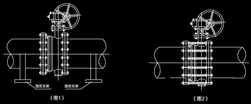
4、伸缩蝶阀刻在任意位置安装,做温度补偿用时,在管道安装完成后,需沿管道轴线方向两端加支架,
防止伸缩阀伸缩管拉出(见图1),支架的支承力俺下列公式计算,运行时严禁将支架卸掉
式中:PS-管道试验压力,DN-管道直径
5、伸缩蝶阀不做温度补偿时,只做安装更换、维修阀门方便用时可用通螺栓限位,对称夹紧伸缩蝶阀以防止伸缩管拉出(见图2),损坏伸缩蝶阀及管道装置或建筑物。螺栓直径可按照法兰螺栓直径,其螺栓强度和承受试验压力及管道拉力,按上公式进行计算,运行时限位螺栓晋严禁卸掉(螺栓另配)
6、管道施工现场严禁随意拆卸接替伸缩蝶阀。
7、本伸缩蝶阀,加工精细,配合严密,请勿在现场随意反复拉长压短伸缩蝶阀。管道安装时,要求伸缩蝶阀两端管道必须同心,管道上的两法兰面要求平行。
8、法兰固定螺栓应对称紧固,请勿单边强行紧固法兰固定螺栓。
9、伸缩管安装在阀门后。
10、伸缩阀伸缩部分不得安装在管道拐角处或管道末端。
1.Telescopic butterfly valve should be placed horizontally,any collision will be notallowed.
2. When telescopic butterfly valve left factory,its structure length is the minimum length,when installation should be pulled toinstallation length (Design length).
3.When length between pipes exceed telescopic valve installation length,please adjustthe space between pipes,shouldn't pull telescopic valve constrainedly,lest damage telescopic valve.
4.Telescopic butterfly calce can e installed in optional position,when it copmpensatetemperature,after install pipe,it should be installed brackets on both sides of pipe axes direction,in order to prevent telescopic tube oftelescopic valve from pulling out (see diagram1),accumulate supporting force of bracket should be according to formula as below,and shouldn't unload bracket when de ivery.
Test:PS-pipe pressure test,DN-Diameter of pipe
5.When telescopic butterfly valve doesn't treat as temperature compensation ,only treat as install,exchange,and maintain valve conveniently,and it can use screw to retain,and clamp telescopic butterfly valve symmetrically,so as to avoid telescopictube being pulled out (see diagram2),and damage telescopic butterfly valve and pipe fitting orconstruction,Diameter of bolt can according to diameter of flange bolt,accumulate bolt intensity and bearing pressure test and pull of pipe according toabove formula,when poeration,retaining screw shold not be unloaded mate in addition.
6.On pipe constructive spot where remove or disassembly telescopic butterfly bvalve will be not allowed.
7. This kind of telescopic butterfly valve has beem machining and fitting strictly,don't pull and press it from time to time optionally on spot.When install pipe,Both
pipe ends of telescopic valve should be homocentric,both facing flanges should be horizontal.
8.Fixed bolt on flange should be smmetrical andclamped,shouldn't clamp fixed boltof flange on single side.
9.Telescopic tube should be installed behind of valve.
10.Telescopic part of telescopic valve shouldn;t be installed on corner of pipe orend of pipe.

